

CN
EN
JP
KR
KR
CN
EN
JP
KR
KR
Most UAV teams do not discover latency problems from a specification sheet.
They discover them during testing.
The aircraft is connected.
The video is visible.
Telemetry is still updating.
Control commands are still going through.
But the timing no longer feels fully aligned.
The operator begins to compensate. The engineering team starts checking interfaces, signal paths, processing delays, and link behavior. What looked like a small communication detail becomes a debugging problem.
That is why UAV communication latency should be reviewed before field testing begins.
Not because every UAV system needs the same latency target.
Not because one number explains the entire architecture.
But because timing problems become harder to solve once they appear inside a working UAV system.
For teams building UAV control, telemetry, video, or payload links, low latency is useful only when the team understands where that latency is measured and what the number actually includes.
Latency is often treated as a simple specification.
Lower is better.
Faster is better.
A smaller number looks more competitive.
But UAV systems do not experience latency as one isolated number.
They experience it as part of a timing loop:
When these signals do not stay aligned, the issue is no longer only “delay.”
It becomes control uncertainty, testing friction, and integration risk.
A latency problem found early is an engineering variable.
A latency problem found late is often a project delay.
That is the practical reason to review UAV communication latency before field testing.
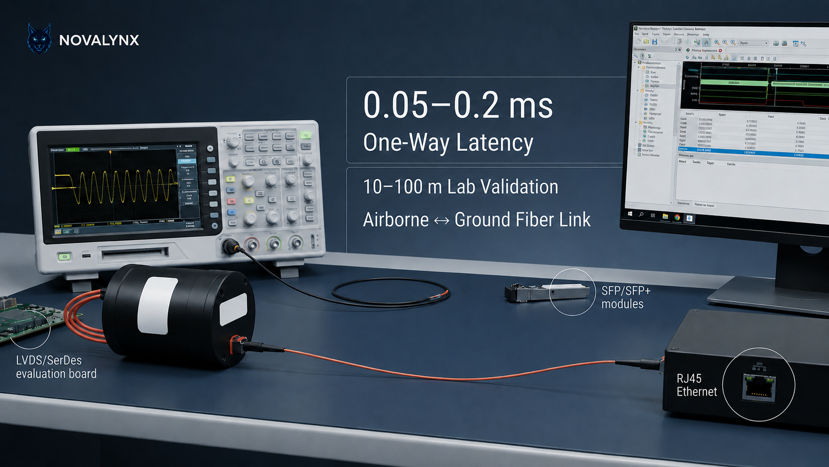
NovaLynx fiber transceiver systems support 0.05–0.2 ms one-way latency across the airborne-to-ground fiber transceiver link under standard lab test conditions.
This latency refers to the core optical-electrical transmission path between the airborne fiber transceiver unit and the ground-side fiber transceiver unit.
The measured path includes:
• Electrical signal input
• Transmitter-side electrical-to-optical conversion
• Fiber transmission
• Receiver-side optical-to-electrical conversion
• Electrical signal output
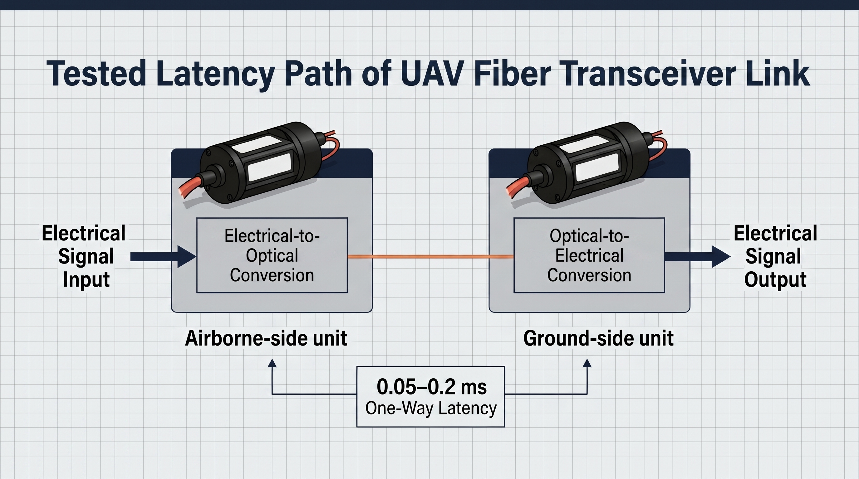
It also includes the core protocol encoding and decoding process within the transceiver link.
In other words, the stated latency covers the transceiver body + fiber channel.
It should not be interpreted as the total latency of the complete UAV system.
The 0.05–0.2 ms value does not include external UAV system components such as:
This distinction is important.
A UAV video system, for example, may include camera capture, encoding, transmission, decoding, rendering, and display output. The fiber transceiver link is only one part of that full chain.
The value of a low-latency fiber transceiver is that it helps keep the transmission layer lean, so it does not consume unnecessary timing margin from the rest of the UAV system.
For UAV integrators, the better question is not only:
What is the latency number?
The better question is:
Which part of the system does this latency number describe?
The 0.05–0.2 ms latency range is based on a pure fiber transceiver transmission link between the airborne side and the ground side.
The core optical side commonly uses SFP / SFP+ optical interfaces, which are suitable for compact and lightweight airborne deployment.
The electrical-side connection may use:
In UAV fiber video and data transmission scenarios, airborne-side systems often use LVDS because of its low-voltage, interference-resistant, low-latency signal characteristics. Ground-side systems may use Gigabit Ethernet / RJ45 / onboard GE for data output and integration.
Standard lab validation is typically performed with fiber lengths from 10 m to 100 m:
| Fiber Length | Purpose |
|---|---|
| 10 m | Baseline latency reference |
| 50 m | Common lab simulation distance |
| 100 m | Extended lab simulation distance for ground-station-to-launch-point deployment |
Within this 10–100 m range, the inherent propagation delay of the fiber itself is extremely low and does not materially affect the 0.05–0.2 ms latency range.
The stated 0.05–0.2 ms value refers to one-way transmission latency.
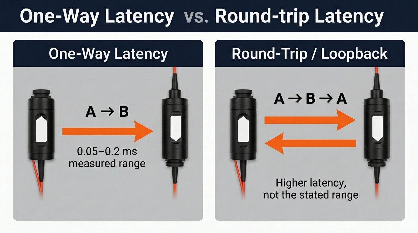
That means the signal travels from the transmitting end to the receiving end once:
It is not a round-trip or loopback latency value.
A round-trip test would include signal transmission from A to B and return transmission from B to A:
That result would naturally be higher and should not be confused with the stated one-way latency range.
For UAV teams comparing latency values, this distinction matters. A one-way transceiver-link latency value and a full round-trip system latency value are not the same measurement.
A useful latency review should look beyond one headline number.
Different measurements answer different engineering questions. Confusing them can lead to wrong expectations during integration.
| What to Check | Why It Matters |
|---|---|
| One-way latency | Shows the signal delay in one direction |
| Round-trip latency | Helps evaluate command-response timing |
| Jitter | Shows whether timing stays stable or fluctuates |
| Test boundary | Clarifies what is included in the latency measurement |
| Interface type | LVDS, Gigabit Ethernet, RJ45 / onboard GE, and SerDes may affect system integration |
| Fiber length | Transmission distance affects propagation delay |
| Signal type | Control, telemetry, video, and payload signals have different timing needs |
| Test load | Latency may change when data demand increases |
| External processing | Video encoding, decoding, rendering, and flight controller response add system-level delay |
This is where many communication reviews become too shallow.
A team may know the latency number but not the test boundary.
They may know the interface but not whether the value is one-way or round-trip.
They may know the transmission delay but not how the rest of the UAV system contributes to total timing.
That is why latency should be reviewed as a system question, not just a product specification.
Latency can enter the system at multiple points.
A simplified UAV communication path may include:
• Control / video / telemetry / payload input
• Interface conversion
• Protocol handling
• Fiber transceiver link
• Signal processing
• Flight controller / payload / ground station
• Feedback loop
The fiber transceiver link is only one part of the total path.
But it is a critical part.
If the transmission layer is slow, unstable, or difficult to predict, the whole system has less timing margin. That can affect how the operator experiences control, how telemetry is interpreted, and how confidently video feedback can be used.
If the transmission layer stays low-latency and predictable, the system has more room for the unavoidable delays created by cameras, encoding, decoding, displays, processing, and control logic.
This is the real value of low-latency fiber communication.
It helps prevent the transmission layer from becoming the bottleneck.
Average latency is useful.
But it is not enough.
A link with low average latency can still create problems if timing varies too much from moment to moment.
That variation is jitter.
For UAV systems, jitter can be more difficult to manage than fixed delay because the timing becomes less predictable. One signal arrives quickly. The next one arrives later. The next one arrives at a different interval.
That inconsistency can affect:
A simple way to understand it:
Average latency shows speed. Jitter shows whether timing can be trusted.
For UAV communication, both matter.
Fiber optic communication does not create zero latency.
No communication system does.
Its value is different.
Fiber provides a physical optical transmission path that is less exposed to electromagnetic interference than RF links. For UAV systems operating in interference-sensitive environments, this can help make communication timing more controllable.
That matters because UAV communication problems are not always caused by complete link failure.
Sometimes the link remains active, but timing becomes less reliable.
Control still works, but response confidence weakens.
Video still appears, but timing becomes harder to trust.
Telemetry still updates, but not with the consistency the system needs.
A fiber transceiver link helps reduce this kind of timing uncertainty at the transmission layer.
This is why low-latency fiber communication should not be evaluated only as a speed feature.
It should be evaluated as part of the system’s timing architecture.
NovaLynx fiber transceiver systems support 0.05–0.2 ms one-way latency across the airborne-to-ground fiber transceiver link under standard lab test conditions.
For UAV teams, the value is not simply the number.
The value is that NovaLynx helps keep the airborne-to-ground fiber transmission layer low-latency, so it does not consume unnecessary timing margin from the total UAV system.
This can support timing-sensitive links such as:
NovaLynx also supports UAV-oriented fiber transceiver configurations using SFP / SFP+ optical interfaces and electrical-side options such as LVDS, Gigabit Ethernet, RJ45 / onboard GE, and SerDes, depending on project requirements.
That matters because low latency is only useful if the communication link can fit into the system.
A fast link that creates integration problems is not enough.
A low-latency link needs to work with the signal type, interface, fiber length, transceiver configuration, and mission requirement.
That is where a latency review becomes practical.
Need to evaluate where fiber transceiver latency fits into your UAV communication chain? NovaLynx can help review fiber length, interface type, signal requirements, and airborne-to-ground transmission timing before field testing begins.
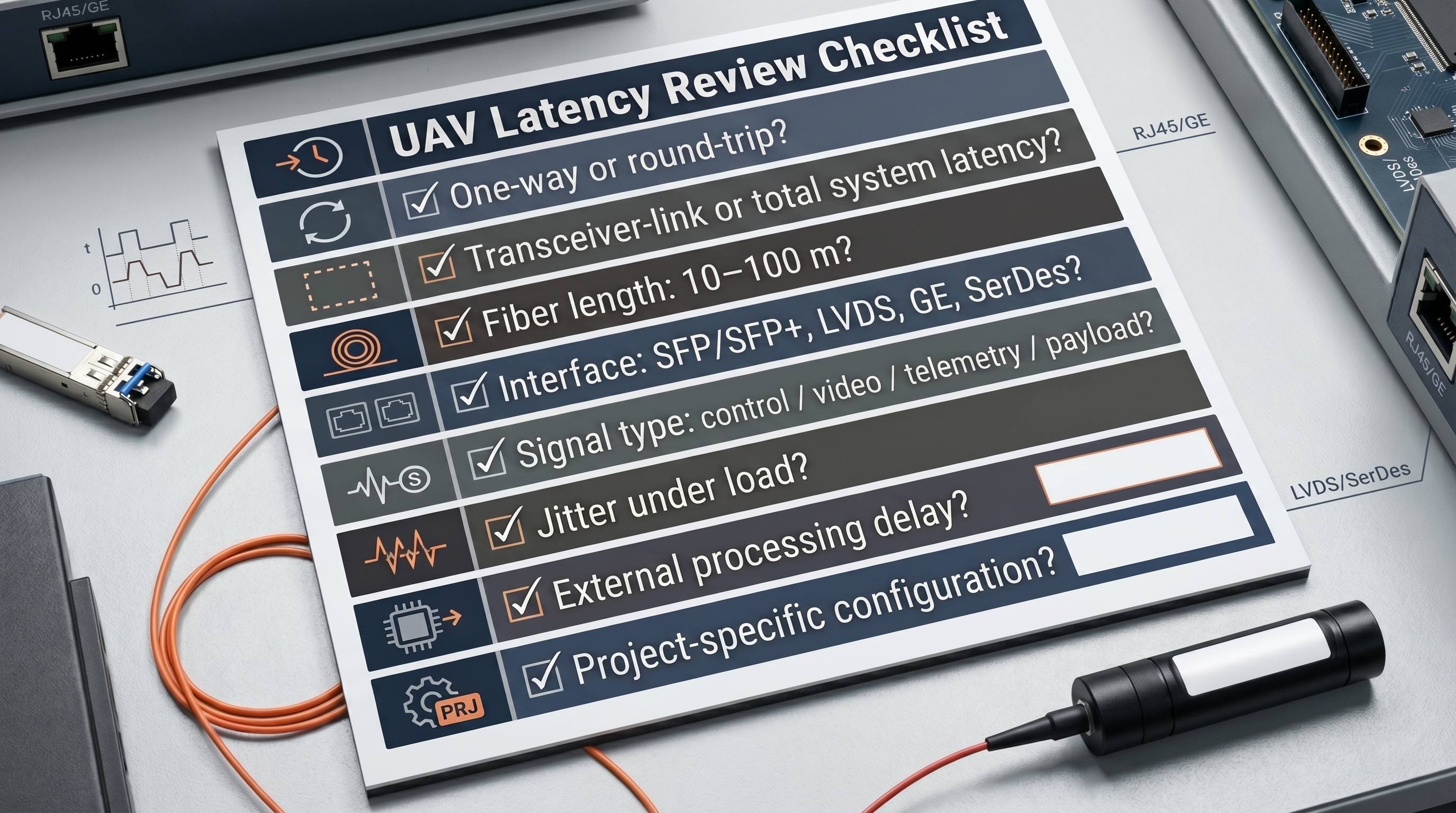
Before selecting or integrating a low-latency fiber transceiver link, UAV teams should review the questions below.
| Review Question | Why It Matters |
|---|---|
| Is the latency one-way or round-trip? | Avoids misunderstanding the number |
| Is it transceiver-link latency or total system latency? | Defines the real test boundary |
| Which interface is used? | Different interfaces require different signal handling |
| What fiber length is required? | Distance affects propagation delay |
| Which signals are timing-sensitive? | Control, video, telemetry, and payload data differ |
| Does timing remain stable under load? | Reveals jitter, buffering, or processing risk |
| What external processing is added? | Encoding, decoding, rendering, flight control, and payload response add system delay |
| Is the communication layer consuming too much latency budget? | Helps avoid integration delay later |
| Does the supplier support project-specific configuration review? | Reduces uncertainty before system testing |
This checklist helps move the discussion from a claim to an engineering decision.
It also helps UAV teams avoid one of the most common problems in communication design:
reviewing latency only after the system has already been built.
For technical buyers, low latency alone is not always enough to justify a supplier decision.
The stronger buying signal is the combination of:
This is where NovaLynx is positioned.
The 0.05–0.2 ms latency range gives UAV teams a strong starting point. But the more important value is how that transmission performance fits into the full UAV communication architecture.
For a team building a timing-sensitive UAV system, the question is not:
Who has the lowest number on a page?
The better question is:
Which communication link reduces timing uncertainty without creating new integration risk?
It refers to one-way latency across the airborne-to-ground fiber transceiver link.
The measurement covers the core transceiver and fiber channel, including electrical input, transmitter-side electrical-to-optical conversion, fiber transmission, receiver-side optical-to-electrical conversion, protocol encoding/decoding inside the transceiver link, and electrical output.
It does not represent the total latency of the complete UAV system.
No.
The stated latency does not include flight controller processing, video encoding, gimbal control, wireless relay, backend decoding, video rendering, display delay, or other external system components.
Those elements may add additional system-level latency depending on the UAV architecture.
It is one-way transmission latency from the transmitting end to the receiving end.
It is not a round-trip or loopback latency value. Round-trip latency would include signal transmission from A to B and return transmission from B to A, so the result would be higher and should not be confused with the stated 0.05–0.2 ms range.
Standard lab validation is typically performed with fiber lengths from 10 m to 100 m.
A 10 m link can be used as a baseline reference, while 50 m and 100 m links can simulate common ground-station-to-launch-point deployment distances.
Within this range, the inherent propagation delay of the fiber itself is extremely low and does not materially affect the 0.05–0.2 ms latency range.
The optical side commonly uses SFP / SFP+ optical interfaces.
The electrical-side connection may use LVDS, Gigabit Ethernet, RJ45 / onboard GE, or SerDes depending on the system configuration. Airborne-side systems often use LVDS, while ground-side systems may use Gigabit Ethernet for data output and integration.
Latency is the delay in signal transmission.
Jitter is the variation in that delay.
For UAV systems, jitter matters because inconsistent timing can reduce confidence in control, telemetry, video, or payload feedback.
Teams should review latency type, test boundary, interface type, fiber length, signal type, load condition, jitter behavior, and the total UAV system timing budget before field testing.
Low latency is valuable.
But in UAV systems, low latency becomes much more useful when teams understand where it is measured and what it includes.
NovaLynx fiber transceiver systems support 0.05–0.2 ms one-way latency across the airborne-to-ground fiber transceiver link, helping UAV teams keep one critical part of the system timing chain lean, predictable, and easier to evaluate before field testing.
The goal is not just a lower number.
The goal is a communication link that supports control, telemetry, video, and payload timing without becoming the hidden source of integration delay.
If your UAV system depends on real-time control, telemetry, video feedback, or payload coordination, communication latency should be reviewed before field testing begins.
NovaLynx can help evaluate how low-latency fiber transceiver performance fits into your UAV communication architecture, including fiber length, interface type, signal requirements, and airborne-to-ground transmission timing.
Request a UAV Low-Latency Communication Review
When contacting NovaLynx, please include your UAV platform type, required fiber length, signal type, interface requirement, and current communication challenge. This helps our team review the most suitable low-latency fiber communication option for your system.
Request a UAV Low-Latency Communication Review
Edited by NOVALYNX on May 2026
NovaLynx helps customers solve interference and communication reliability challenges in complex UAV and mission-critical scenarios. Our solutions cover fiber optic systems, anti-jamming communication modules, and tailored integration support based on real operational needs.